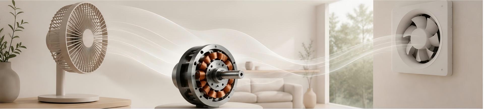
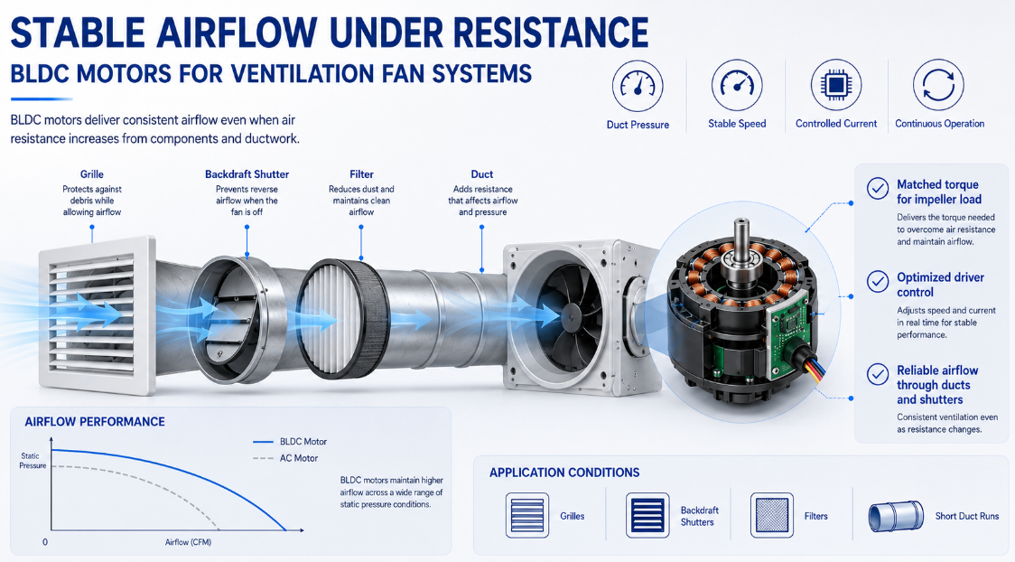
A ventilation fan must continue moving air through grilles, shutters, filters, wall openings, and ductwork. These components create airflow resistance and increase the load placed on the motor. A motor that performs normally in open air may lose speed, generate excessive heat, or become noisier after installation inside the completed fan.
For this ventilation fan project, customized BLDC Motors were developed around the actual impeller, housing, airflow path, and control requirements. The objective was to improve airflow stability while maintaining compact dimensions, controlled temperature rise, and reliable continuous operation.
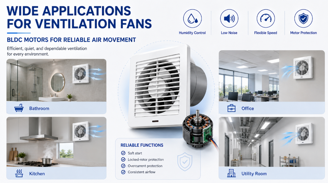
The customer was developing a compact ventilation fan for bathrooms, kitchens, utility rooms, offices, shops, and other residential or light commercial spaces.
The original motor provided basic exhaust performance but offered limited speed control. Its operating temperature also increased when the fan was connected to a duct or fitted with a backdraft shutter.
The new motor solution needed to provide:
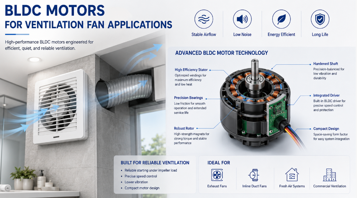
Reliable starting under impeller load
Stable airflow through ventilation ducts
Lower vibration and operating noise
Multiple speed or airflow settings
Controlled temperature during long operation
Compact dimensions for the existing housing
Protection against blocked rotation
Consistent performance in volume production
After reviewing the installation structure and operating conditions, a customized BLDC motor for ventilation fan applications was selected.
Ventilation fan performance is closely related to static pressure. Air resistance rises when the fan works through a narrow outlet, filter, long duct, protective grille, or backdraft shutter.
When resistance increases, the motor may need more torque to maintain the required rotational speed.
The impeller diameter, blade angle, weight, and rotational resistance determine the motor load. Selecting the motor only by rated wattage may result in poor starting performance or unstable airflow.
During this project, the ventilation fan motor was tested with the actual impeller. The winding parameters and driver program were adjusted to provide sufficient starting torque without creating unnecessary current consumption.
The matching process considered:
| Motor Factor | Ventilation Fan Requirement |
|---|---|
| Starting torque | Sufficient to start the installed impeller |
| Rated speed | Matched to the required airflow |
| Operating current | Controlled under normal duct resistance |
| Shaft size | Compatible with the impeller hub |
| Rotation direction | Selected according to blade design |
| Motor dimensions | Fitted within the existing housing |
| Driver settings | Configured for the required speed levels |
This approach helped the motor maintain stable performance after the grille, shutter, and ventilation duct were installed.
A ventilation fan may operate normally during open-air testing but experience a noticeable speed drop after installation.
The customized brushless DC exhaust fan motor was tested under different airflow resistance conditions. Driver settings were refined to reduce speed fluctuation and maintain more consistent exhaust performance.
This was especially important for applications requiring long ducts or automatic shutters, where the motor faces greater resistance than an open circulation fan.
One of the main advantages of BLDC Motors is electronic speed regulation. The motor driver can control rotational speed more accurately than traditional winding-based adjustment.
For this project, the customer required different airflow levels for normal ventilation, rapid exhaust, and quiet operation.
The motor system can be configured to support:
Low-speed continuous ventilation
Standard daily exhaust
High-speed rapid air extraction
Humidity-controlled operation
Timer-based ventilation
Sensor-controlled starting
Stepless speed adjustment
Low-speed operation is useful when continuous air exchange is required without excessive noise. High-speed operation can provide stronger exhaust when moisture, heat, smoke, or odors increase.
The variable speed ventilation motor maintained stable rotation at each operating level and allowed smoother transitions between different speeds.
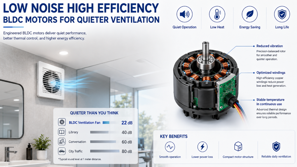
Ventilation fans are often installed in bathrooms, bedrooms, offices, and other occupied spaces. Motor vibration can transfer to the housing, ceiling, wall, or duct and make the fan sound louder than expected.
Noise may come from:
Rotor imbalance
Bearing movement
Shaft misalignment
Electromagnetic vibration
Impeller imbalance
Housing resonance
Air turbulence through the grille
For this application, the rotor balance, bearing fit, shaft dimensions, and driver frequency were reviewed together.
The motor mounting position was also matched to the internal bracket to reduce vibration transfer. After adjustment, the fan operated more smoothly across the required speed range.
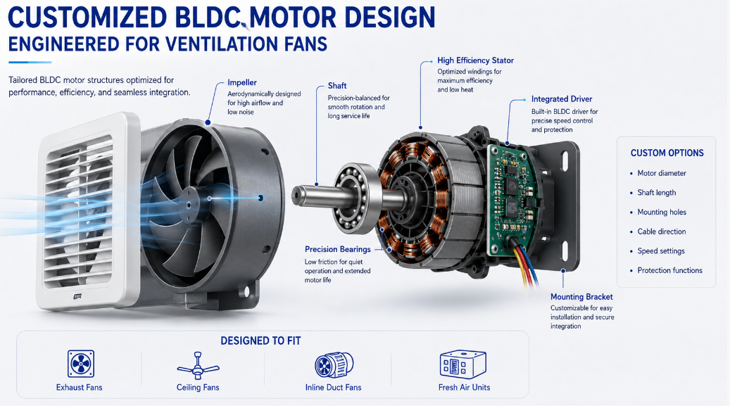
The customer wanted to retain the existing ventilation fan housing. This meant the new motor had to fit within a limited installation space.
The shaft diameter and extension length were customized according to the impeller hub. Correct shaft dimensions helped maintain stable impeller positioning and reduced the risk of contact with the housing.
The mounting holes were aligned with the existing bracket, reducing the need to modify plastic moulds or assembly tooling.
Cable direction was also adjusted to keep wiring away from the rotating impeller and simplify final assembly.
Depending on the fan structure, the driver can be integrated with the motor or installed separately inside the housing.
For this project, the driver was configured to communicate with the customer’s control system and support the required speed settings. The control program also included smooth acceleration to reduce sudden mechanical impact during starting.
Ventilation fans may run for several hours or remain active throughout the day. Motor temperature is therefore an important part of application testing.
The motor was evaluated inside the completed housing because restricted ventilation and nearby plastic components can affect heat dissipation.
Testing included:
Winding temperature rise
Driver component temperature
Motor current at each speed
Bearing operating condition
Temperature under duct resistance
Extended high-speed operation
Repeated start and stop cycles
The customized energy efficient fan motor provided the required torque while limiting unnecessary electrical loss. This helped maintain a more stable temperature during continuous operation.
Ventilation fans may encounter abnormal conditions caused by dust accumulation, a blocked impeller, damaged shutters, or foreign objects entering the housing.
The motor driver can include several protection functions:
Locked-rotor protection
Overcurrent protection
Overvoltage protection
Low-voltage protection
Thermal protection
Controlled restart
Abnormal load detection
Locked-rotor protection was particularly important for this project. When the impeller could not rotate normally, the driver limited prolonged current rise and helped protect the motor winding and electronic components.
After the motor samples were installed, the entire ventilation fan assembly was tested rather than evaluating the motor separately.
The fan was tested with its grille, shutter, and duct connection installed. Motor speed, current, airflow, and temperature were recorded under different resistance conditions.
Low-speed testing confirmed that the motor could maintain continuous rotation without hesitation or repeated restarting. Noise and vibration were also checked because mechanical sounds are often more noticeable at reduced airflow levels.
The ventilation fan operated for extended periods at different speeds. The test confirmed that the motor and driver remained stable under the expected working conditions.
Repeated cycles were used to evaluate the driver, bearings, shaft connection, and impeller mounting. This test was relevant for fans controlled by timers, humidity sensors, or occupancy sensors.
After the winding parameters, shaft structure, and driver program were adjusted, the ventilation fan achieved more stable performance under actual installation conditions.
The final motor solution provided:
Reliable starting with the installed impeller
More consistent airflow through ducts and shutters
Stable low-speed ventilation
Reduced motor vibration
Controlled temperature during continuous use
Flexible electronic speed adjustment
Better compatibility with the existing housing
Protection against abnormal operating conditions
The customized motor also reduced later production adjustments because the mounting points, wiring direction, speed curve, shaft dimensions, and control settings were confirmed before batch manufacturing.
To develop suitable BLDC Motors for ventilation fan products, buyers should provide complete application information, including:
Impeller diameter and weight
Blade structure and rotation direction
Required airflow and speed range
Expected static pressure
Rated voltage and power supply
Housing and mounting dimensions
Shaft diameter and length
Control signal requirements
Continuous operating time
Noise and temperature targets
Required protection functions
Testing with the actual impeller and housing is recommended because motor performance can change after the complete airflow system is assembled.
The role of BLDC Motors in ventilation fans extends beyond basic rotation. Electronic speed control, stable torque output, compact construction, smooth starting, and configurable protection functions help manufacturers develop ventilation products for different installation environments.
A suitable BLDC motor for ventilation fan applications should be matched to the impeller load, duct resistance, housing space, airflow requirement, and control system. Through customized windings, shafts, mounting structures, driver programs, and protection settings, the motor can support reliable operation throughout the service life of the ventilation fan.
Previous: Pedestal fan
Next: